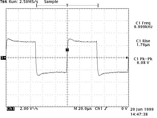
A in comparison almost ideal 6.5Vp-p/10kHz square wave signal (tr=500ns) was injected into both primary windings connected in series and thru a 2.5kOhm resistor (simulating two KT66 type push-pull tubes as driving source) and measured at primary windings with 8Ohm connected at the secondary. This signal thereby represents the actual transformer driving voltage and as such also indicates a low leakage inductance and thus a high frequency response (0.35/1.76us=200kHz approximately@4% overshot) and even more importantly, a total freedom from HF oscillating problems!
The overshot is due to the use of this special type of core which has a wider B/H-loop than standard cores (see for instance my testresults for the TI-87060) and therefore can withstand more direct current or bias unbalance before saturation.
Back